Bridge Weigh In Motion: How accurate is it?
Keywords: BWIM, Heavy Goods Vehicles, weight measurements, bridge selection, COST323
1 Introduction
This paper discusses when BWIM can be applied and how accurate it is. We will outline how BWIM works and why it needs accurate measurements. We describe how accuracy is assessed, the type of bridges to which BWIM may be applied and the conditions that need to be fulfilled. The relevant specifications are defined in the COST 323 document: we will summarise the points most relevant to BWIM. Finally, we will describe the approach to accuracy we have pursued in iBWIM and the level of accuracy we have achieved.2 Bridge Weigh in Motion: Accuracy Issues
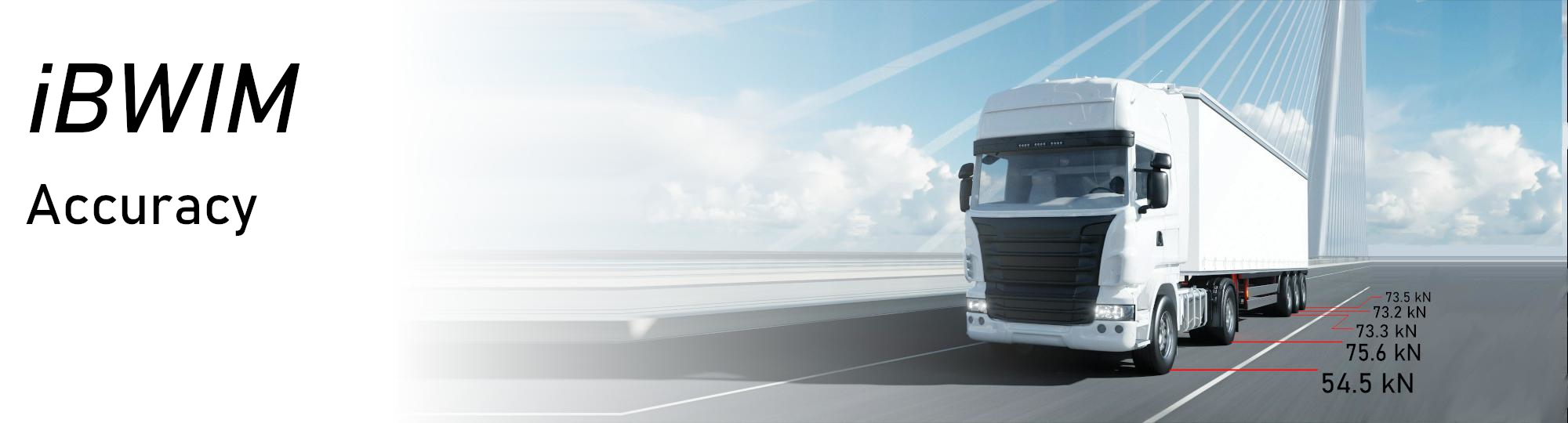
Bridge Weigh In Motion (BWIM) infers the force exerted by the axles of a vehicle by measuring how they deform the bridge. Strain gauges are mounted on the underside of the bridge; their response is linearly related to the force applied by the axle. With calibration data it is possible to calculate the weight of each of the vehicle's axles.
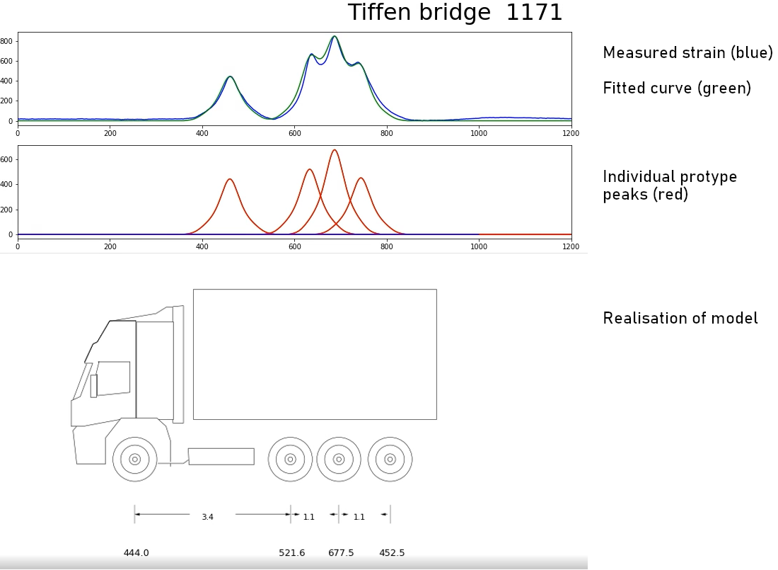
As a load passes over a strain sensor the measured strain rises and then declines. For a given vehicle, a series of axles results in a series of ovelapping peaks in the strain signal. The measurement algoithm works by fitting a combination of prototype peaks to the signal. The algorithm varies the number of peaks, their amplitude and position to obtain the best match to the signal. By measuring the location and amplitude of each prototype peak, the algorithm estimates the position and weight of each axle.
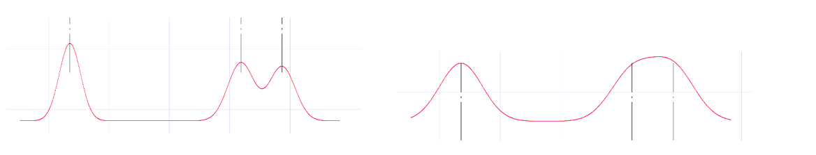
The degree of overlap between the peaks depends on the characteristics of the bridge and the vehicle. For instance, on long bridges, multiple axles contribute to the signal, and several peaks may merge. In this case there may be several axle patterns that explain the measurement equally well. That is, it may not be possible to resolve the peaks and correctly measure individual axles. The range of bridges to which a BWIM system can be appllied depends on the system's ability to resolve the contribution of each axle. This in turn depends on:
- the characteristics of the bridge;
- the layout of the sensors;
- the quality of the electronics, and
- the resolving power of the estimation algorithm.
The characteristics of the bridge largely determine the difficulty of weight estimation. A short, stiff bridge will deform less than a long bridge and will give a weaker signal; a long, flexible bridge will deform more, but strain peaks will overlap more and will be harder to resolve. Long bridges are also more prone to harmonics which, if not suppressed, may confound the fitting algorithm.
The type of bridge construction is also critical for the performance of BWIM:
- Frame bridges are optimal due to their rigidity and the lack of bearings.
- Beam girder bridges are optimal with the proviso that they do not use bearings. Rubber bearings introduce dampling and vibration modes that may degrade system performance. For multibeam (prefabricated bridges) each beam must be instrumented.
- Steel box girder bridges present difficulties because the torsional effect between lanes makes it difficult to resolve each lane.
- Slab bridges are sub-optimal due to the influence of the second lane. Suitable where there is only one lane, or the second lane is rarely used by HGV traffic.
- Compound bridges many bridges contain elements from more than one of the above categories. Often these elements can be treated as isolated "sub-bridges" and we can instrument the most appropriate section of the bridge. For instance, we have achieved good results on a steel box girder bridge that had central slab sections. These were isolated and could be instrumented independently.
The accuracy of the measurements and the resolving power of the algorithm determine the range of bridges to which BWIM can be rigorously applied.
3 COST323
3.1 Introduction
The COST323 specifications were developed to give manufacturers and users of Weigh In Motion systems a common framework for discussion and comparison. COST 323 is not an official standard, but has gained acceptance in the WIM community in Europe. It defines accuracy classes, measurement requirements and vehicle classes. This section summarises the points relevant to Bridge Weigh In Motion, it is of course our interpretation and [1] remains the authoritative text.
Weigh in Motion systems are a pragmatic solution to a real-world problem. They measure the impact of vehicle axles on a bridge. As such they are affected by the interaction of the vehicle's suspension and the local characteristics of the bridge, neither of which is entirely deterministic. They are therefore, by their nature, not traceable to international measurement references. Instead, the COST323 standard was developed to account for the statistical nature of the measurement. The standard defines 5 accuracy classes by application and specifies tolerances within a 95% confidence interval.
3.2 Cost323 Accuracy Classes
| Class | Tolerance (95 % Confidence) | Application |
|---|---|---|
| A(5) | ± 5 % | Legal purposes, reference measurements |
| B+(7) | ± 7 % | Enforcement of legal weight limits, with reduced accuracy with special dispensation from legal authorities. |
| B(10) | ± 10 % | Infrastructure maintenance, preselection of overloaded vehicles, vehicle type identification. |
| C(15) | ± 15 % | Detailed statistical studies, load histograms with bin sizes of or 2 tonnes, classification of vehicles, fatigue assessments. |
| D(20) | ± 20 % | Detailed statistical studies, load histograms with bin sizes of or 2 tonnes, classification of vehicles, fatigue assessments |
| D(25) | ± 25 % | Statistical purposes, economic and technical studies, vehicle classification. |
3.3 Measurement Sites
Classes of Measurement Site
Since the bridge or road forms part of the measurement system, COST323 also specifies the acceptable road geometry. Obviously it is not possible to conduct the most accurate measurements at a relatively poor site. Measurement sites are classified into three classes, The table below shows the site requirements for the different accuracy classes.
| Accuracy Class | Site I | Site II | Site III |
|---|---|---|---|
| A(5) | Sufficient | Insufficient | Insufficient |
| B+(7) | Sufficient | Insufficient. | Insufficient. |
| B(10) | Sufficient | Sufficient. | Insufficient. |
| C(15) | Overspecified | Sufficient. | Sufficient. |
| D(20) | Overspecified | Overspecified. | Sufficient. |
| D(25) | Overspecified | Overspecified. | Sufficient. |
Site Criteria
The class of a site is determined by whether it fits the following criteria: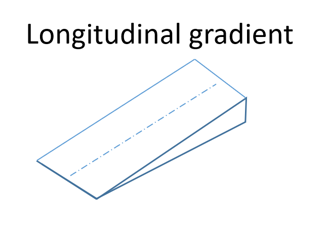

Classes of Measurement Site
Since the bridge or road forms part of the measurement system, COST323 also specifies the acceptable road geometry. Obviously it is not possible to conduct the most accurate measurements at a relatively poor site. Measurement sites are classified into three classes, The table below shows the site requirements for the different accuracy classes.
| Criterion | Site I | Site II | Site III |
|---|---|---|---|
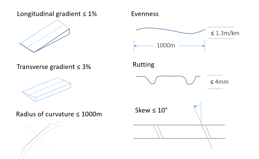
| Longitudinal Slope | < 1 % | < 2 % | < 2 % |
| Transverse Slope | < 3 % | < 3 % | < 3 % |
| Radius of curvature | < 1000m | < 1000m | < 1000m |
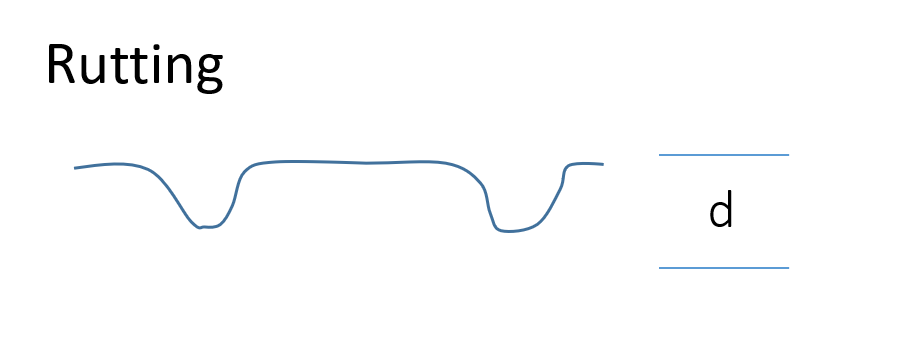
| Rutting depth (max.) | < 4mm | < 7mm | < 10mm |
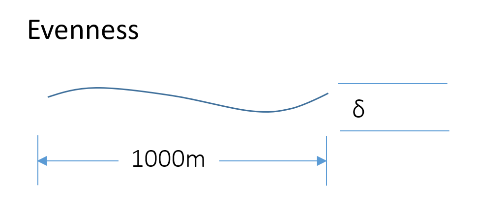
| Evenness (m/km) | 0 to 1.3 | 1.3 to 2.6 | 2.6 to 4.0 |
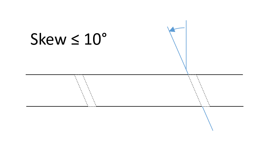
| Skewness | < 10 ° | 10 ° to 30 ° | > 10 ° |
Bridge Requirements:
COST323 defines the following types of bridge optimal for BWIM:- Steel girder
- Pre-stressed concrete girders
- Reinforced concrete girders
- Culvert
- Steel orthotropic decks
3.4 Vehicle Classes
The standard also defines eight categories of vehicle:| Category | Description |
|---|---|
| 1 | Cars, cars + trailers/caravans and vans (35kN) |
| 2 | Two axle rigid lorry |
| 3 | Rigid lorries with more than two axles |
| 4 | Tractor with a semi-trailer which is supported signle or tandem axles |
| 5 | Tractor with a semi-trailer which is supported by tridem axles |
| 6 | Lorry with trailer |
| 7 | Busses |
| 8 | Other vehicles |
4 iBWIM and Accuracy
4.1 Strategy
Our iBWIM system adopts several approaches to maximise accuracy. First, we use our own proprietory strain gauges with an innovative mechanical design, on-board temperature compensation and smart self-calibration of the sensors. Second, we use high frequency, high bit resolution sampling. This reduces noise, but also picks up subtle nuances that help the fitting algorithm resolve overlapping peaks. If necessary we apply signal processing techniques to suppress harmonics which might otherwise mislead the fitting algorithm. Finally, depending on the bridge, we may also use complementary measurements such as laser axle detection and velocity measurement to improve the quality of modelling.
4.2 Requirements for Road Geometry
Applied to suitable bridges iBWIM system can achieve A(5) class measurements.
We define the following prerequistes for the measurement sites:
| Bridge Class | 5m to 10m | 11m to 23m | 24m to 35m | > 36m |
|---|---|---|---|---|
| Slab | A(5) | B(7) | ||
| Frame | A(5) | B(7) | ||
| Beam | B(7) | B(10) | C(15) | |
| Steel Box Girder | B(10) |
5 References
[1] COST 323 "Weigh-in-Motion of Road Vehicles", Final Report, Appendix I European WIM SpecificationEditors: Bernard Jacob, Eugene O'Brien and Sophie Jehaes